


 |
Post and wire systems are a cost effective, versatile and completely humane bird deterrent. Post and wire provides an ideal solution for ornate building facades where the anti perch system's visual impact is an important factor to be taken into consideration.
Each system works by positioning thin steel wires, tensioned with springs, just above a ledge or other feature that is used by birds as a roost. The wires present a physical barrier and the unstable feel of the spring-loaded wires will deter all but the most persistent birds.
The wires are held in position by vertical stainless steel posts which can be inserted into 25mm masonry rivets or surface mounted in plastic bases.
Post and wire can also be attached to rails, gutters and steel beams using specially designed posts which can be clamped to the desired object.
Each run of wire should be tensioned at each end by a short wire attached to a stainless steel screw pin and plug.
|
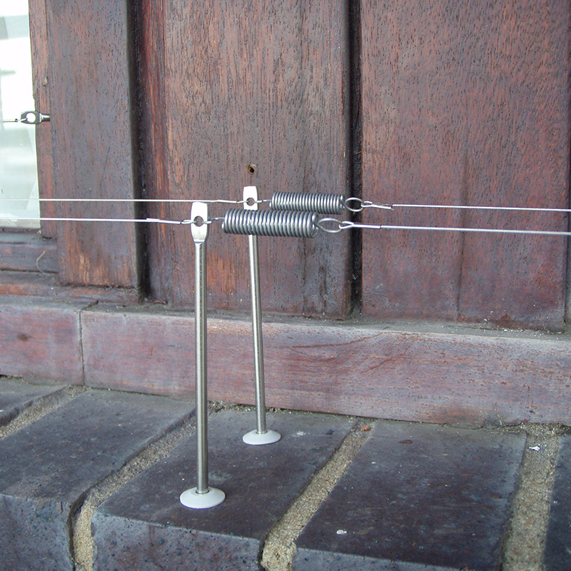
Begin each run of post and wire with a suitable anchor point |
|
|
Each run of post and wire should be anchored at each end to spread the load of the tensioned wires. For masonry this is done with a screw pin and wall plug. For plastic, metal and glass use a surface mount base. |
|
|
Install your first post and attach it to the anchor point |
|
|
Leaving a gap of 115mm for pigeon posts and 150mm for seagull posts install the first post. For masonry use a 25mm rivet and for plastic, metal and glass use a surface mount base to hold the post. Next run a short length of wire from the anchor point to the eye in the top of the first post, securing the wire at each end with a crimp. 0.45mm pigeon wire is secured using nickel crimps. 0.96mm seagull wire is secured using 1.0mm copper crimps. |
|
|
Installing subsequent posts. |
|
|
Leaving a gap of up to 1.5 metres for pigeon wire and up to 3 metres for seagull wire install your next post. Attach a spring to the eye at the top of the newly installed post. Measure and cut a length of wire approximately 10 centimetres longer than the space between the first and second posts. Secure one end of the wire to the eye in the top of the first post. Then loop the other end of the wire through the spring on the second post. Apply a small amount of tension to the wire so that the spring is slightly stretched and crimp the wire to the spring. Repeat this process until you reach the end of the ledge to be protected. |
|
|
Finishing the run |
|
|
At the end of the run install a second anchor point similar to the one at the beginning of the run. |
|
|
Spacings, widths, lengths: |
|
|
Please refer to the charts below before attempting your post and wire installation to ensure you have the correct products, quantities. |
|
| MASONRY & TIMBER | PIGEONS | SEAGULLS |
|---|---|---|
| Post Anchorage Method | PestFix 25mm Masonry Rivet (PW209 or PW210) or directly into timber with 4mm X 20mm hole | PestFix 25mm Masonry Rivet (PW209 or PW210) or directly into timber with 4mm X 20mm hole |
| Height of front / leading edge wire | 90mm | 160mm |
| Post size to be used on leading edge. | 115mm X 4mm dia. single head (PW204) for low-pressure. 130mm X 4mm dia. double head (PW205) for medium pressure. | 180mm X 4mm dia. single head (PW226) |
| Height of wire in subsequent rows | 110mm | 160mm |
| Post size to be used on subsequent rows. | 130mm X 4mm dia. single head. (PW214) | 180mm X 4mm single head (PW226) |
| Linear distance between posts | Max 1.5m apart, can be less, but use a min of one spring per 1.5m run. | Max 3m apart, can be closer, but use a min of one spring per 3m run. |
| Distance between parallel rows of wire | 35mm for second row then 65mm max for subsequent rows | 100mm max |
| Spring type | PestFix Standard Spring (PW207) | PestFix Micro Spring (PW227) |
| Wire type | 0.45mm dia. Plastic coated to 0.70mm dia., breaking load 24.5 kg (PW200, PW201, PW202 & PW203) | 0.96mm dia. non-coated, breaking load 93kg. (PW225, PW249, PW250 & PW251) |
| Crimp type | PestFix Nickle Plated Crimps (PW208) | PestFix 1mm Copper Crimps (PW228) |
| Crimp tool | PestFix Post & Wire Crimp & Cut Tool (PW241) | Ratchet Crimp Tool (NT118 or NT143) |
| SURFACE MOUNTING | PIGEONS | SEAGULLS |
|---|---|---|
| Post Anchorage Method | PestFix Surface Mount Base (PW219, PW220, PW221 & PW222) can be glued or screwed into position. | PestFix Surface Mount Base (PW219, PW220, PW221 & PW222) can be glued or screwed into position. |
| Height of front / leading edge wire | 90mm | 150mm |
| Post size to be used on leading edge. | 90mm X 4mm dia. single head (PW215) for low-pressure. Do not use double-head posts with surface mount bases. | 150mm X 4mm dia. single head (PW231) |
| Height of wire in subsequent rows | Alternate between 90mm & 115mm | 150mm |
| Post size to be used on subsequent rows. | Alternate between 90mm X 4mm dia. single head (PW215) and 110mm X 4mm dia. single head. (PW204) | 150mm X 4mm single head (PW231) |
| Linear distance between posts | Max 1.5m apart, can be closer, but use a min of one spring per 1.5m run. Parallel posts must not line-up and should be staggered | Max 3m apart, can be closer, but use a min of one spring per 3m run. Parallel posts must not line-up and should be staggered |
| Distance between parallel rows of wire | 35mm for second row then 65mm max for subsequent rows | 100mm max |
| Spring type | PestFix Standard Spring (PW207) | PestFix Micro Spring (PW227) |
| Wire type | 0.45mm dia. Plastic coated to 0.70mm dia., breaking load 24.5 kg (PW200, PW201, PW202 & PW203) | 0.96mm dia. non-coated, breaking load 93kg. (PW225, PW249, PW250 & PW251) |
| Crimp type | PestFix Nickle Plated Crimps (PW208) | PestFix 1mm Copper Crimps (PW228) |
| Crimp tool | PestFix Post & Wire Crimp & Cut Tool (PW241) | Ratchet Crimp Tool (NT118 or NT143) |
PestFix
Unit 1-3 Cedar Park
30 Terminus Road
Chichester
West Sussex
PO19 8GT
Sales Enquiries
Tel: 01903 538 488
Fax: 01903 539 331
Email: [email protected]
Press Enquiries (Journalists Only)
Email: [email protected]
 |  |
|
|
|
|